In the videos above I explain how a typical single boiler machine is built, how it works, and why I connected the wires here and there, using a Rancilio Silvia and a Gaggia Classic as examples. The first video is specially important if you are installing your PID in a different machine, for you to understand what you are looking for inside your machine, e.g. if you will remove only the brew thermostat or also the steaming one, and to avoid all the mistakes that I and some colleagues made, saving some time, money and frustration.
The importance of temperature stability and precision
Temperature plays a critical role in espresso extraction. Temperature fluctuations can significantly impact the flavor profile of your coffee.
Standard thermostats in domestic machines are often not precise enough, leading to temperature swings that can make your espresso taste inconsistent. Its main function is activating the heating element at the designed temperature range.
However, they often allow for significant temperature fluctuations—sometimes as much as 10-15 degrees—which can result in over-extraction (bitter) or under-extraction (sour) within the same shot.
Replacing the thermostat by a PID controller is a game-changer. A PID (Proportional-Integral-Derivative) provides precise temperature management by monitoring the boiler temperature every second and making real-time corrections, as soon as a slight temperature change is detected and actively pursues the target.
The result is a very stable extraction temperature, within a very narrow range, typically within 1-3 degrees variation along the extraction, depending on the characteristics of your machine. My Rancilio Silvia is in the 1-2 range, my ECM Classika PID in the 1-3 Celsius degree range, and my Gaggia Classic in the 4-5 degrees band.
To add a PID to your single boiler espresso machine you can follow the guides below (this is just the initial version and will continuously be updated with more videos, pictures, better organization of the information, and details for specific machines).
Index
- The Bill of Materials
- Installation process for XMT 7100 (only brew) in a Rancilio Silvia
- What if I want to control the steaming temperature also with my PID (Silvia)?
- Testing (Silvia) – very important!
- Basic Operation of your PID XMT 7100
- Installing the REX C100 PID controller (Silvia)
- Installing the REX C100 PID in a Gaggia Classic
- Examples of PID settings for different machines
The Bill of Materials
The complete list of components, consumables and tools needed can be found here.
In the comments, I also added a few reminders about these specs, alternatives, pros and cons. It’s very easy to get confused and buy the wrong version or voltage or size, so I highly recommend checking the comments or reading the detailed information about the BOM below, but feel free to skip to the step-by-step procedure.
1.PID Controller options:
a. REX C100:
Pros: this is the cheapest option, with two lines, one for the target temperature and the other for the actual temperature. It’s more convenient to adjust the temperature, just press “Set” for a few seconds and the arrows to increase or reduce the target temperature, in the XMT 7100, you have to enter a code, scroll down/up the menu, chose the target temperature, then adjust it. I find it annoying. There are much more offers available and more documentation as well. PS: if you want to use the PT100 sensor, check first if your model is compatible.
Cons: the size can be considered a downside. Some consider the XMT 7100 more elegant.
b. XMT 7100:
Pros: slimmer, more elegant solution, may be the only option if you have limited space where you want to install.
Cons: it is more expensive, circa 4x times more (circa 40 USD against 10 USD for the REX C100), much more buttons to press for any operation. PS: if you want to use the PT100 sensor, check first if your model is compatible.
c. Auber PID Kit:
Pros: Auber became very popular and some companies like Seattle Coffee Gear sell Rancilio Silvias with the Auber PID kit pre-installed if you wish. It has one starter version for USD 150 and another with pre-infusion, shot timer, and steam temperature control for USD 200. In the kit, a comprehensive manual and pre-crimped cables are included.
Cons: it is super expensive to my view considering that you can buy the whole kit, consumables and the tools needed for less than USD 100, depending on the quantities and the tools you already have circa USD 50 will suffice. The pre-infusion function is very limited, it is just a few seconds of pump on, then another seconds off, and then the extraction begins lasts for the set duration (you can configure the pre-infusion pulse, i.e. the time the pump will work initially; the soak time (the time if will be off for the puck to get soaked); and the brew time, but I prefer the gradual increase/decrease flow/pressure rate that we can achieve with a dimmer. Another detail that many people don’t like, including me, is that the pre-infusion function release the pressure in the puck during the pause for infusion (the solenoid valve goes off). Do some research about pre-infusion, pressure/flow profiling and take your decision.
2. SSR:
This is the component that will switch the heating element on and off, commanded by the PID controller. What you need to pay attention:
a. Load current: there are 10A, 25A, 40A and more. I recommend at least the 25 A, however, 40 A is more common and may be included in some kits.
b. Input voltage: your PID controller uses DC voltage to command the SSR, then the input in your SSR needs to be DC.
c. Output voltage: this is the phase that is connected to your heating element, then it need to be AC. Then, choose the 3-32 VDC in and 24-380 VAC out.
3. Thermocouple
a. Types: type K is the most common, cheaper, with more options (threaded or washer and others), with 1 Celsius degree precision. Type PT100 you fill mostly find the threaded version but may allow a more precise temperature (0.1 C degree) if your PID is compatible with PT100.
b. Enclosure: I prefer the “hole washer” version. The real sensor is a very small metallic ball (circa 1mm in diameter) fit in a washer, or inside a threaded cylinder, round tip, and others. My preference for the washer version is that you can install it under the thermostats with great surface contact, well fixed, compatible with most machines (I don’t know of any single boiler that doesn’t have at least one thermostat in the boiler). If you want to use the threaded version, I recommend the M3 for Rancilio Silvia and M4 for Gaggia Classic, since you can replace one of the screws that fix the thermostats in a Rancilio or the whole thermostat in a Gaggia.
4. Wires:
I recommend at least AWG 16 / 1.5 mm2 (for up to 13 A) and multiple colours. Ideally, 5 or 6 colours, and 3 would be the minimum that I recommend, to avoid mistakes in the installation, especially because at some point you will close the machine and only the wires will be visible externally when you are connecting to the PID. You can always label, however, buy 1-2 colours only and save a few bucks.
5. Connectors:
These are recommended, but not mandatory. You can cut some wires, solder and isolate, but the spade/piggyback connectors will lead to a cleaner, more professional, reversible installation. The downside is that it is more laborious, and I’d recommend buying a crimper tool which will add about 10 bucks to the costs. Some people that are not comfortable with soldering can cut the wires and use Wago connectors. Just pay attention to the thickness of the wires (some are for up to 2.5 mm2, others for 4 mm2 and the AWG 16 will be loose in the connector which is a short circuit hazard).
6. Thermal compound (or thermal paste):
It’s good practice to wipe the surfaces and add new thermal compound. I didn’t test without it, it may not affect, but I highly recommend applying it since you don’t want to troubleshoot and reopen your machine later.
7. Housing:
You can use a 3d printed version or an aluminium enclosures available on Aliexpress. There are enclosures for PID, Dimmer and Pressure gauge integrated for Gaggias and I designed one for Rancilio SIlvia and made it available on https://makerworld.com/en/@espressohackers. Depending on how handy you are, you can also cut the panel to install both the PID and the pressure gauge, but this is for the advanced DIYers.
a. Philco 15/20 bar: Internal installation: you can also download the some great models from my friend Jonny Stayle here for internal installation. It may fit other machines, if you have enough internal space.
b. Vibiemme Domobar: I already designed a simple version for PID + dimmer in https://makerworld.com/en/models/560435.
c. Gaggia Classic: I found an option but notice that it’s for a 40 mm pressure gauge: https://www.printables.com/model/140834-gaggia-housing-for-pid-controller-and-pressure-gau.
d. Rancilio Silvia: if you want a simple version, there’s one here: https://makerworld.com/en/models/684319
8. Tools:
a. Crimper and Cable Cutter: this is an optional but very useful tool. You can use pliers or scissors to stripe the wire, and some pliers can be used to crimp the connectors, however, my personal experience is that I lost a bunch of connectors and time re-striping/re-crimping wires. 10 dollars, in my case, was a smart investment, I just regret not having bought before.
b. Multimeter: there are alternatives such as using a led, battery and some wires if you just want to check your connections, or voltage detector pens combined for specific uses such as checking if the SSR is opening/closing. However, multimeters are so cheap nowadays and multipurpose, a tool that you can use for many applications later right after seeing a 5 min youtube video that I recommend also as a smart investment.
c. Multibits toolkit: I hate having to stop what I’m doing to go to the hardware store and buy that only bit or allen key that I don’t have. Then, I bought one of these kits, but depending on what you already have, you might not need, or buy just a set of allen keys or precision screwdrivers of better quality for the same price.
9. Others:
Philips and flathead screwdrivers, allen keys, adjustable wrench, check which fasteners you have in your machine. Electrical insulation tapes or heat shrink tubing and hot air gun.
Installation process for XMT 7100 in a Rancilio Silvia (controlling only the brew temperature):
Preparation
1. For your safety, unplug your espresso machine. If you just brewed a coffee, let it cool down.
2. Take pictures or make videos of the disassembling process or you may not remember the sequence to reassemble, or which nuts and bolts go where.
3. Remove the drip tray and the water reservoir.
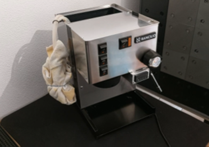
4. Remember that the hoses will leak and you don’t want any drop of water in any electrical part. In general, I use a cloth and a rubber band:
5. Open your machine to get access to the pump. I showed how to open a Rancilio Silvia here: https://youtu.be/gGiFi3-Vb6w
6. Simulate the position of the PID and the SSR.
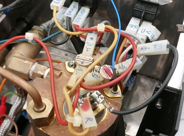
7. Before disconnecting any wire, label all of them:
Measuring, cutting, crimping and connecting the wires:
1. Remember that you will have to pass all the wires coming from the machine into a hole to the outside, then into a hole into the enclosure of your PID and through the lid of the casing, and then connect the wires below to your PID. This sequence is specially important for the common Aliexpress enclosure for XMT 7100, but pay attention to the specifics of the box/installation you chose.
2. Red: with a piggyback connector to be installed in the out of the Power button. Then, the energy will be delivered to its original connector and also to power the PID in the pin 1 (fork connector).
3. Black: from the safety thermostat (female spade connector) to a piggyback connector to split the energy for the PID and the heating element. I recommend using a point after the Overheat Protection Thermostat so that you can benefit from this protection also for your PID.
4. Black: from the previous piggyback connector to the PID (fork connector), pin 2.
5. Red: from the piggyback connector in 2 (Power Button) to the heating element (female connector to fork connector).
6. Black: from the piggyback connector in 3 to the heating element (female connector to fork connector).
7. Red: from the red wire that was entering the Brew Thermostat (male spade connector) to the SSR (fork connector), pin 1.
8. Red: from the SSR (fork connector to male spade), pin 2, to the connector that was attached to the gray wire, in the other end of the Brew Thermostat (male spade connector, and you are now bypassing the thermostat).
9. Yellow: with a fork connector from the SSR pin 3 to the PID pin 10 (fork connector).
10. Green: with fork connectors in both ends again, from the SSR pin 4, to the PID pin 9.
11. Thermocouple Type k: connect the negative terminal to the Pin 6 in the XMT 7100, and the positive to the Pin 7. If you see an error message in the reading, most likely you connected the thermocouple to the wrong pins.
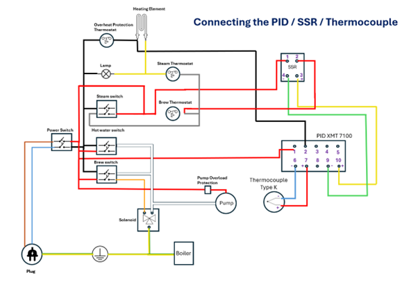
Schematics for XMT 7100, Thermocouple type K, PID controlling only the brew temperature
12. Thermocouple Type PT100 (if your PID is compatible also with PT100, check the spec): there are two equal wires (in general the connectors are red) that shall be connected to the PID, Pins 6 and 8; and the different wire (in general a blue connector) to the pin 7. If you see an error message in the reading, most likely you connected the thermocouple to the wrong pins.
13. To install the Thermocouple in the boiler, just replace one of the screws that is fixing the thermostat to the boiler by the threaded version of the thermocouple there. If it is a Rancilio Silvia, it is a M3 threaded thermocouple, if it’s a Gaggia Classic, a M4.
13.1. Washer type: I particularly prefer this one because you can install it under the thermostats with great surface contact, well fixed, compatible with most machines (I don’t know of any single boiler that doesn’t have at least one thermostat in the boiler). Remember to put some thermal paste around your sensor.
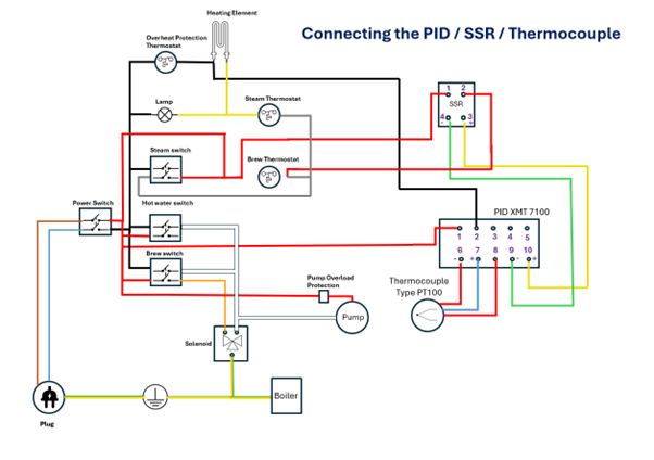
Schematics for XMT 7100, Thermocouple type PT100, PID controlling only brew temperature
What if I want to control the steaming temperature also with my PID (in a Silvia)?
One option is to disconnect also the steam thermostat and connect the SSR straight to the heating element. In this case, the sequence will be:
Measuring, cutting, crimping and connecting the wires:
1. Remember that you will have to pass all the wires coming from the machine into a hole to the outside, then into a hole into the enclosure of your PID and through the lid of the casing, and then connect the wires below to your PID. This sequence is specially important for the common Aliexpress enclosure for XMT 7100, but pay attention to the specifics of the box/installation you chose.
2. Red: with a piggyback connector to be installed in the out of the Power button. Then, the energy will be delivered to its original connector and also to power the PID in the pin 1 (fork connector).
3. Black: from the safety thermostat (female spade connector) to a piggyback connector to split the energy for the PID and the heating element. I recommend using a point after the Overheat Protection Thermostat so that you can benefit from this protection also for your PID.
4. Black: from the previous piggyback connector to the PID (fork connector), pin 2.
5. Red: from the piggyback connector in 2 (Power Button) to the heating element (female connector to fork connector).
6. Black: from the piggyback connector in 3 to the heating element (female connector to fork connector).
7. Red: from the red wire that was entering the Brew Thermostat (male spade connector) to the SSR (fork connector), pin 1.
8. Red: from the SSR (fork connector), pin 2, to the yellow wire, into the connector that was attached to the other end of the Steam Thermostat (male spade connector, and you are now bypassing both thermostats). You can also remove the gray wire now.
9. Yellow: with a fork connector from the SSR pin 3 to the PID pin 10 (fork connector).
10. Green: with fork connectors in both ends again, from the SSR pin 4, to the PID pin 9.
11. Thermocouple Type k: connect the negative terminal to the Pin 6 in the XMT 7100, and the positive to the Pin 7. If you see an error message in the reading, most likely you connected the thermocouple to the wrong pins.

Schematics for XMT 7100, Thermocouple type K, PID controlling brew and steam temperature
12. Thermocouple Type PT100 (if your PID is compatible also with PT100, check the spec): there are two equal wires (in general the connectors are red) that shall be connected to the PID, Pins 6 and 8; and the different wire (in general a blue connector) to the pin 7. If you see an error message in the reading, most likely you connected the thermocouple to the wrong pins.
13. To install the Thermocouple in the boiler, just replace one of the screws that is fixing the thermostat to the boiler by the threaded version of the thermocouple there. If it is a Rancilio Silvia, it is a M3 threaded thermocouple, if it’s a Gaggia Classic, a M4.
13.1. Washer type: I particularly prefer this one because you can install it under the thermostats with great surface contact, well fixed, compatible with most machines (I don’t know of any single boiler that doesn’t have at least one thermostat in the boiler). Remember to put some thermal paste around your sensor.

Schematics for XMT 7100, Thermocouple type PT100, PID controlling brew and steam temperature
Tests (highly recommended, at least two friends tripping the circuit breaker due to short circuits in their PID mods):
1. Using a multimeter: you need to set you multimeter to continuity test or maximum scale of resistance (2M symbol):

1.1. Plug the red probe to oCVΩmA and the black probe to COM.
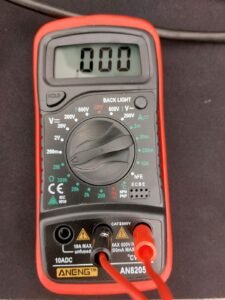
2. The first thing you want to check is if there’s any short circuit in your installation. So let’s test with your machine unplugged. However, the pump, the solenoid valve and the heating element have windings that will lead you to wrong conclusions, so first, disconnect one terminal of each of those components.
2.1. With all the buttons off, and after disconnecting the electromagnetic components and heating element
2.2. Connect the two probes to your plug. If you see 1, press the power button. You must see 1 again in your multimeter. If you see 0, there’s a short circuit and you need to review your installation.
3. Testing the power to the PID (still with the power button on):
3.1. With one probe connected to one of the pins of your plug, and the other to the pin 1 or 2 of your PID, you have to see 0 in one of the pins.
3.2. Then, connect the one probe to the other pin of your plug and the other plug to 1 or 2 of your PID, again, you need to see 0, but in the other pin, not the one that you saw 0 in 3.1. This means that your PID is powered by the Power button.
4. Testing the pump connections
4.1. When you press the extraction button, the pump should be on. Then, connect one of the probes to one of the pins in your plug, and the other to one of the wires connected to the pump, and if you read 1, connect it to the terminal that you disconnected for the tests. In one of them, you need to see 0.
4.2. Connect the probe to the other pin in your plug, and again you will connect the other probe to the terminals in the pump and shall find a 0 in one of them.
4.3. Power off the extraction button and power on the heat water button. Repeat the tests in 4.1 and 4.2.
5. Testing the connection to the SSR:
5.1. With all the other buttons off and only the Power button on, connect one probe to one of the pins of your plug, and the other to pin 1 of your SSR, if you don’t see 0, connect the probe to the other pin in your plug. One of them should be delivering power to your SSR.
6. Now, the risky tests. We’ll test the connections to the PID and SSR. Do it only if you know what you are doing. Otherwise call a professional. You will connect the plug to electricity, with your machine open, and lots of places for you to get a shock, which can be deadly.
6.1. Power off all the buttons.
6.2. Reconnect the pump, heating element and solenoid valve.
6.3. Plug your machine to an outlet.
6.4. Power on your machine. If your circuit breaker didn’t trip, this is good news. The PID shall be on now, and you need to see the temperature reading. If there’s an error in your PID, you probably inverted the connections of your thermocouple, turn your machine off and review the installation.
6.5. You also need to feel the boiler heating, except if your PID is set to a very low temperature. But instead of touching the boiler, you can see if the led in your SSR is on or blinking, which means that the PID is commanding it.
6.6. If the led in the SSR is not on or blinking, check the target temperature in your PID and if below room temperature, increase it to 50 Celsius degrees, for example. Now the led in your SSR shall be blinking. And also the very small led “AT” in your PID.
6.7. If the led “AT” in your PID is blinking and the SSR is not, check the connections of the pins 3 and 4 in your SSR to the PID (with the machine off and unplugged).
7. Now, the boiler shall be heating. And it is time to test the pump. Extra attention now, with the water getting out of the group.
7.1. Make sure the valve of your steam wand is not open.
7.2. Place a bowl or similar under the group. Press the extraction button on and you need to see your pump working and delivering water from the group. Turn it off.
7.3. Press the hot water button and open the valve of your steam wand. If it delivers water from the steam wand, all good. Close the valve and turn the hot water button off.
8. If you let the steam commanded by the thermostat, you may want to test it now:
8.1. Press the steam button and see if the temperature in your PID is increasing above the 95 Celsius degrees. For this test, if you had set 90 degrees for example, you can reduce to room temperature. First, you just want to see if the temperature is not being limited by the PID. Second, it needs to go beyond 95 degrees, to check if the brew thermostat is not liming the temperature (you should have disconnected the brew thermostat, but what if you disconnected the wrong one? In this test, you just need to see the temperature going beyond the target you had set in your PID).
9. The last test that I recommend: close the PID box, and if it is in aluminium, I’d repeat the short circuit testing (disconnecting pump, heating element and solenoid again and testing the pins in your plug with the power button off, and after powering on).
10. If all the previous tests were successful, unplug your machine, fix the SSR with screws or double face tape, and close your machine.
10.1. Reminders: you may want to install the dimmer or pressure gauge later. Plan for the future mods before fixing the SSR.
10.2. You need some space to fix/remove the wire and tighten the screws. Check if your tools / hands can reach the spaces.
11. Attach the PID enclosure to your machine, with the double face tape or the whatever you planned to use, and for a better finishing, you can use a sleeve cable to organize the multiple wires going to your PID.
11.1. In a Rancilio Silvia, there is a classic position under the front panel that can obstruct the movement of the steam wand. Check before fixing and consider installing the PID on the lateral or in a top box. By the way, I am designing a top box for dimmer, pressure gauge and PID combined for Rancilio Silvia and will make it available in https://makerworld.com/en/@espressohackers
Basic operation of your PID XMT 7100
1. Setting the target temperature
1.1. Press (SET), then enter code “0001”, press (SET) again.
1.2. Using the arrows, scroll down to Sv and press (SET).
1.3. In Sv, set the desired temperature using the arrows and press (SET).
1.4. Using the arrows, scroll up to End and press (SET).
2. Setting offset, Thermocouple type and Temperature unit:
Press (SET), then enter code “0089”, press (SET) again, and scroll down or up to access the different parameters. The main ones are:
2.1. Offset (PSb):
In my Rancilio Silvia, I set the offset to -14 Celsius degree. Ideally, you should measure the temperature in your portafilter while brewing a shot and see the difference between your set value and the real temperature in the coffee puck. I measured with a thermometer paired with a thermocouple type k, putting the probe in the portafilter with coffee ground for espresso 1:2 ratio, 30s, and I found the 14 degrees difference.
2.2. Thermocouple type (Inty): check in your manual in case you are using the PT100. The default is type k.
2.3. Unit (CorF ): 0 for Celsius and 1 for Fahrenheit.
3. Setting P, I, and D:
Press (SET), then enter code “0036”, press (SET) again, and scroll down or up to access the different parameters, and adjust P, I and D following the procedure below (4).
3.1. There is an auto-tunning function, but in my experiences, the fluctuation was very high and I don’t recommend using this function. However, if you want to try, press and hold (>) until “AT” indicator blinks, which indicates auto-tuning is in progress. It will take a few minutes, maybe around 15 (I don’t exactly remember). When it finishes, “AT” indicator will go off and the newly calculated PID parameters will be stored. To stop the auto-tuning in progress, press and hold (>) until “AT” indicator turns off. The previous PID parameters will not be changed.
4. Fine tunning
My settings: P: 1.0; I: 400; D: 10. You can start with these settings if you have a Rancilio Silvia.
If your machine is different, I suggest to start with 1.0 in P, 300 in I and 0 in D.
Your machine shall be at room temperature. A heated boiler will interfere in your calibration. For each test, you will have to let the machine cool down before a new trial.
First, let’s adjust P and I.
4.1. After turning your machine on, measure how long it takes to achieve the set temperature. It will probably exceed the set value going upper and lower a few times, observe how much is the deviation. I don’t stay in front of my machine when I’m calibrating, I film the PID for 15-30 min and see the video later.
4.2. You want to achieve the desired temperature in 7-10 min. I don’t remember how much was the fluctuation until I was satisfied with P and I. If it’s taking too long to achieve the set temperature, increase P (but below 2.0). Then, test different values for I, e.g. 300, 350 and 400, and observe the behaviour.
Now, let’s adjust the parameter D:
4.3. After choosing the best combination of P and I, increase D to 5-10, and the fluctuation shall be reduced. The temperature shall be stable within 1 Celsius degree variation in less than 15 min.
Installing the REX C100 PID controller (Silvia)
For the REX C100, the main difference is the pinout. I’ll leave the schematics for both the type K and PT100, but only for the PID controlling the brew temperature. If you want to control also the steaming temperature, the connections will be the same as in the procedures above, and the SSR and Thermocouple connections to the PID will be the same as below:

Schematics for REX C100, Thermocouple type K, PID controlling only the brew temperature
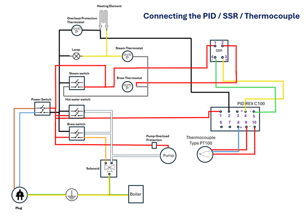
Schematics for REX C100, Thermocouple type PT100, PID controlling only the brew temperature
Installing the REX C100 PID controller in a Gaggia Classic
For the preparation and disassembling process, please check my post about descaling where I show step by step how to do it or the respective section in my video about the PID installation in a Gaggia Classic.
Remember to label your connectors before unplugging.
Before the instructions, let me show the electrical diagram that I built to ilustrate the changes that we’ll make. For the pinout reference, please check my video if needed, there’s a section about the the labelling process.

Schematics Gaggia Classic – Original
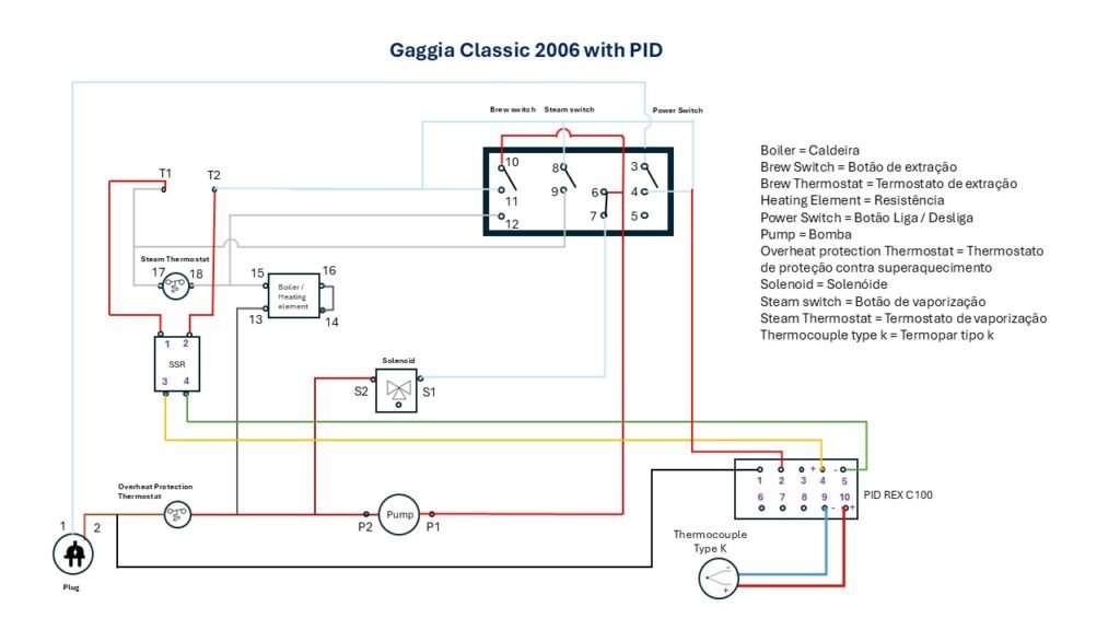
Schematics for REX C100, Thermocouple type K, PID controlling only the brew temperature
Step by step instructions
(I’ll add pictures later, but for now, please check the video to follow the steps below):
- Unplug your machine and remove the drip tray, water tank and discharge pipe.
- Open your machine carefully because the ground wire is attached to the panel.
- Remove the steam knob.
- Losen the steap pipe with a 17 mm wrench.
- Losen the 4 screws with an allen key, 5 mm.
- If you want to disconnect some wires to have more room to play, I just recommend labelling each connector. Otherwise, just incline the boiler to the right, to have a better access to the lateral thermostat which is the brewing thermostat.
- Disconnect the wires attached to the thermostat and remove it with a 17 mm wrench.
- Add some thermal paste to the threads of your thermocouple type K M4 and fix it replacing the thermostat.
- Connect two wires (same color, I used red) in 1 and 2 of your SSR, and two wires with different colours, if you have, to 3 and 4 of your SSR. I used yellow in 3 that is the positive and green in 4 that is the negative.
- Then, connect the red wires (1 and 2) to the terminals that were connected to the thermostat, it doesn’t matter the order.
- Send the yellow and green wires to the outside using one of the holes at the back panel, they will be connected to the PID controller.
- Fix the SSR to the back panel with a M4 screw and nut.
- Send the connectors of your thermocouple to the outside.
- Now, you need two wires (preferably two colours, I used black and red) with a piggyback connector in one end or you will have to cut/join/sold the wires, I prefer the piggyback.
- Remove the brown wire that is connected to the plug and goes to the thermofuse and pump. Connect it to the piggyback and put it back in the plug.
- Remove the black connector in the front switch, on the top, in the steam button. You can also use the terminal in the power button, the terminal that will be activated only when you power on.
- Send both red and black to the external side.
- Now, connect red and black to 1 and 2 in a Rex C100 (REX-C100FK02-V * AN or REX-C100FK02-V * DN), 3 (yellow) to 4 in the PID, and 4 (green) to the 5 in the PID, the blue connector of your thermocouple to 9, and the red to 10.
- You can use double sided tape to fix the PID to the frame
- Test the electrical connections and check for leakages. A basic procedure can be found here.
# | Espresso Machine | PID | Sensor | Tunning | Offset | P | I | D | Comments & Suggestions |
1 | Rancilio Silvia (Espresso Hackers) | XMT 7100 | Type K | Manual | -14 | 1.0 | 400 | 10 | Offset measured with thermocouple type k in the puck. Optimized to achieve the set value as soon as possible and minimizing fluctuation thereafter. |
2 | Vibiemme Domobar (Espresso Hackers) | XMT 7100 | Type PT100 | Manual | -13 | 1.1 | 440 | 50 | Offset measured with thermocouple type k in the puck. Optimized to achieve the set value as soon as possible and minimizing fluctuation thereafter. |
3 | Saeco Poemia (Espresso Hackers) | Rex C100 | Type K | Manual | -12 | 30 | 360 | 8 | Offset measured with thermocouple type k in the puck. Optimized to achieve the set value as soon as possible and minimizing fluctuation thereafter. |
4 | Brasilia Lady | XMT 7100 | Type K | Auto-tunned | -11 | 2.8 | 407 | 101 | The user mentioned an overshoot around 2 Celsius degrees, but "quickly" stabilizing. |
5 | Philco 15 Bar (Espresso Hackers) | Rex C100 | Type K | Manual | -12 | 30 | 360 | 15 | Offset measured with thermocouple type k in the puck. Optimized to achieve the set value as soon as possible and minimizing fluctuation thereafter. |
6 | Gaggia Classic (Espresso Hackers) | Rex C100 | Type K | Manual | -11 | 30 | 360 | 15 | Offset measured with thermocouple type k in the puck. Optimized to achieve the set value as soon as possible and minimizing fluctuation thereafter. |
7 | Gaggia Classic (Set 1 Aubers) | Aubers | Type PT100 | Seller recommendation | -8 | 5.2 | 28 | 7 | Offset recommended by Shades of Coffee, as well as the 3 options of settings, and they prefer the Set 2. |
8 | Gaggia Classic (Set 2 Aubers) | Aubers | Type PT100 | Seller recommendation | -8 | 4.5 | 64 | 16 | Offset recommended by Shades of Coffee, as well as the 3 options of settings, and they prefer the Set 2. |
9 | Gaggia Classic (Set 3 Aubers) | Aubers | Type PT100 | Seller recommendation | -8 | 4.8 | 80 | 20 | Offset recommended by Shades of Coffee, as well as the 3 options of settings, and they prefer the Set 2. |
9 | Oster Primalatte 2 | Rex C100 | Type K | Manual | -3 | 30 | 360 | 12 | User reported that the settings were copied from Philco and work well but may require some fine tunning. |
