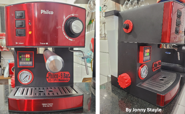
Let’s start with these inspiring pictures of a domestic espresso machine modded with PID, Dimmer, Pressure Gauge and OPV for you to see where we can go in the next posts (not sponsored by Philco)
The easiest modification is the dimmer which enables you to adjust the pump’s flow, and consequently the pressure in the puck. Typically, domestic machines operate at around 15 bars. Reducing the pressure helps to reduce the channeling (water taking the path of least resistance) and ensures a more even extraction. Too much pressure can lead to uneven extraction, where some parts of the coffee puck have more water flowing due to the less resistance that it found and becoming over-extracted (bitter); whilst in other parts less water is flowing and that coffee is under-extracted (sour).
I also posted a video about the process to add a dimmer in a Rancilio Silvia: https://youtu.be/gGiFi3-Vb6w
For a more effective control and measurements, I recommend also adding the pressure gauge, which I will cover in the next post.
Bear in mind that a dimmer will work only in vibratory (electromagnetic) pumps, not on rotary ones. However, if your machine is below the USD 2k, it definitely uses a vibratory pump.

Vibratory pump
Material needed*:
| Item | Quantity | Approximated Cost (USD) | |
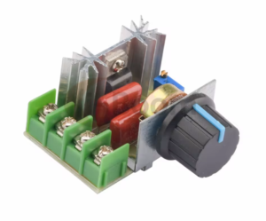 | Dimmer: a vibratory pump in a home espresso machine typically features circa 50W and operates at 110V in the US and 220V in Europe. A dimmer for this application costs circa 2 USD. | 1 | 2,00 |
 | Connectors to splice the wires: in general, I use spade/piggyback connectors, but you can also use Wago 221, twist-on wire cap, butt splice, or soldering and isolating with shrink tube. The easiest is the Wago connector. | 2 | 6,00 for 10 units |
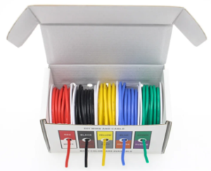 | AWG16 or AWG14 Wires (1.5 – 2 mm2): two pieces of wire with less than 50 cm each, to be measured according to your machine and the position you want to install the dimmer. | 1m | 12 (for 20m) |
| Optional: mounting box for the dimmer, if installed externally. If you want to 3D print, my models are available here for free. And you can also download the models from Jonny here. | 1 |
*I created a comprehensive list of components, tools, accessories, and consumables that you may need in all projects that I’m posting here. This list will be continuously updated with items that I previously verified the specs or used myself, also because lots of people get confused with specs such as power, diameters, materials, models etc. Most of them will be Aliexpress or Amazon affiliate links that will cost you nothing more.
Tools needed:
- You may need to drill a hole in the panel of your machine in order to install the dimmer internally. In this case, you will need a drilling machine and a 6mm drill bit. Another option is to buy or 3D print a box and fix it externally with double sided tape. If you want to 3D print, my models are available here for free. Another option is to buy the enclosure on Aliexpress, however, I bought one that in the end was smaller than the dimmer and it didn’t fit.
- If you use the Wago connectors, a wire cutter and even a scissor will suffice. If you use spade connectors, a crimper and cable cutter will make your life easier.
- Multimeter: recommended to make some tests before connecting the wires.
- Depending on your machine, screwdrivers type Philips, Flathead or Hex will also be needed to disassemble the panels.
Installation process:
- For your safety, unplug your espresso machine. If you just brewed a coffee, let it cool down.
- Take pictures or make videos of the disassembling process or you may not remember the sequence to reassemble, or which nuts and bolts go where.
- Remove the drip tray and the water reservoir.
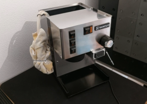
- Remember that the hoses will leak and you don’t want any drop of water in any electrical part. In general, I use a cloth and a rubber band:
- Open your machine to get access to the pump. I’ll illustrate with my Rancilio Silvia here: https://youtu.be/gGiFi3-Vb6w
- Measure and cut 2 pieces of wire, in my Rancilio Silvia one should have circa 50 cm and the other 70 cm. Stripe both ends of each.
- Now we need to find the phase that comes from the extraction/water button: set you multimeter to continuity test or maximum scale of resistance (2M symbol):

- Plug the red probe to oCVΩmA and the black probe to COM.
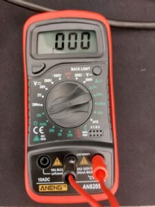
- Unplug one of the wires from the pump and connect one of the probes to it. The other probe shall be connected to one of the pins in your outlet plug.
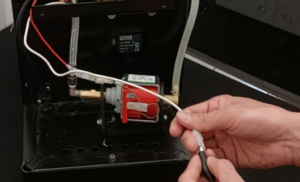
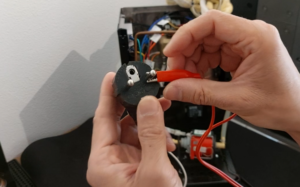
- The buttons shall all be off (Power, Extraction and How Water). and you shall see “1” showing that there is no current flowing. After pressing the extraction or water button, you shall see “0”, showing that now the current is flowing to the pump and this is the wire that we want to split. In my Rancilio Silvia, this wire is white and just for the purpose of clarity in this procedure, let’s call it WHITE WIRE.
- If after pressing the power button (before pressing the extraction button) you already saw “0”, don’t use this wire, but the other.
- Now, you have two options:
- cut the WHITE WIRE and extend the two pieces of wire with WAGO connectors (or similar connectors) connecting each to one of the wires of step 6, being the one that is coming from the extraction button connected to the SHORTER WIRE and the LONGER WIRE to the wire that goes to the pump; or
- use spade/fork connectors: in each wire you can connect one spade (male) and one fork connector. The LONGER WIRE of step 6 you will connect (the male spade) to the pump, and the SHORTER WIRE you will connect (male spade) to the wire coming from the extraction button. I prefer using the spade/fork connectors because it’s more convenient to connect the wires to the dimmer later.
- Mark in the connectors which one is the ” To the Extraction Button”, “To the Dimmer IN” , “To the Dimmer OUT” and ” To the Pump”. You will need to differentiate later. You can also use wires of different colors as well. The dimmer installation is simple but this organization will be more important when installing the PID or the Gaggiuino, hence, I recommend to get used to be more organized.
- Before closing the machine, I recommend to test the dimmer. If something is wrong, you’d better fix before closing the machine, especially the Rancilio Silvia that has several bolts and panels.
- The SHORTER WIRE (no matter if you opted for WAGO or spade/fork connectors) will be connected to the “in” and the LONGER WIRE to the “out”.
- FOR THE TESTING: BE VERY CAREFULL NOW:
- IF YOU ARE MENTALLY TIRED AFTER ALL THE PREPARATION, MAYBE YOU SHOULD MAKE A PAUSE OR TEST THE DAYY AFTER. WHEN THINGS GO WRONG, WE TEND TO RUSH AND TROUBLESHOOTING GETS EVEN MORE CONFUSING.
- PLACE THE WATER RESERVOIR IN A SAFER PLACE ON YOUR TABLE.
- PAY ATTENTION NOT TO TOUCH THE METALIC PARTS OF COMPONENTS. REMEMBER THAT THE BOILER WILL GET HOT IF YOU LEAVE THE MACHINE ON FOR LONG TIME AND YOU MAY GET BURNED.
- KEEP THE CHILDREN AND PETS IN A SAFE DISTANCE.
- PLUG THE MACHINE ONLY AFTER EVERYTHING IS SET UP.
- Put the water reservoir close to the machine, fill with water, remove the cloth from the hoses and immerse them in the reservoir. Check if the hose is not too lose. Use some tape if necessary. Place the dimmer in a safe position as well, where you can command it without touching the live wires. Set the dial in the dimmer to the minimum. Place a bowl or mug under the shower screen.
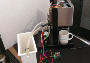
- Plug the cord, turn the machine on, and press the extraction button.
- Turn the knob clock and anticlockwise, observing if the flow is increasing or not.
- If you were able to observe the variation in the flow (you will also hear the noise variation in the pump), you are good to continue. PS: the variation in the noise is normal. In case of doubts, check my video and hear the sound in my machine.
- TURN THE MACHINE OFF AND UNPLUG THE CORD.
- Disconnect the fork connectors from the IN and OUT in the dimmer (only if you are placing the dimmer outside the machine).
- Find the place where you will send the wires out of the machine if you are connecting the dimmer externally. If you are keeping the dimmer internally, try to simulate the place that you will fix it. Make the hole in your panel. Remove the knob and the nut from the dial, place the dimmer and use the nut to fix it from the outside (I show with pictures below how I fixed in the enclosure).
- In you are connecting the dimmer externally and already inserted the two wires through the opening, close the machine.
- If you are using my 3D printed box, insert the cables through the hole in the lid, observing the right side of the lid, remembering that it will slide from left to right.
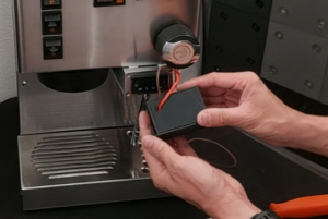
- If you are using fork connectors, bend them 90 degrees to be able to fit the dimmer inside the enclosure. Connect the wires to the IN and OUT in the dimmer.
- Remove the knob and nut, place the dimmer inside the box, fix with the nut outside the box, and close the lid sliding into the position. It may be a bit tight to accomodate the wires:
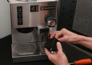
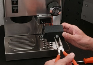
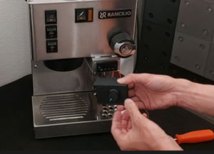
- Test it again.
- Fix the dimmer to your machine.
Just remember that if you do the mods, it’s at your own risk. I take no responsibility for your implementations, I’m only helping with more informed decisions.
